Turbo ABC
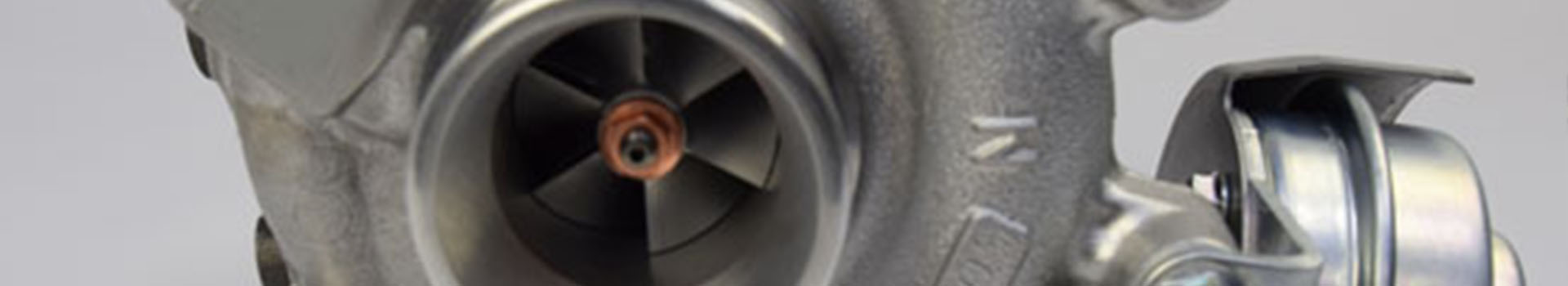
ACTUATOR
An actuator is a devise that operates a control mechanism in the turbocharger. Usually it controls the opening and closing of a waste gate or the nozzle in a VG (variable turbine). Originally, most actuators were pneumatic, so driven by either compressed air or by vacuum. As the demands on closing forces on the waste gates have increased, most actuators are nowadays electrically driven, see e-actuator. Many actuators nowadays also feature a positioning sensor, enabling the vehicle to measure and/or steer the position of the waste gate more accurately.
A/R ratio
The A/R ratio is the area of the volute at a specified location (for example at the tongue) where R is the distance from the turbine axis toward the center of A. The A/R is used during turbine matching. This is because changing the A/R changes the direction of the inflow at the rotor inlet. When increasing A/R the flow will becomes increasingly radial, while decreasing A/R the inflow will be more in the axial direction, which has an effect on the efficiency and flow capacity of the turbine.
BOOST
The pressure delivered by the compressor is sometimes called boost. By increasing the pressure of the air which goes into the combustion engine, its density is increased. The volume of combustion is determined by the bore and stroke of the piston. By compressing the air before it goes into the combustion chamber, its density is increased, thus a larger amount of oxygen is available for combustion.
BURST CONTAINMENT
Turbochargers rotate at extreme rotation speeds. When the turbocharger is exposed to operating conditions far beyond the allowable conditions, the stresses in the wheels may become so high that they break. When a wheel breaks at these extreme rotation speeds, the energy of the moving parts can cause parts to become airborne fragments. In order not to have these fragments cause any damage to the surroundings of the turbocharger, the turbocharger is designed to contain all fragments in case of the explosion of one of the wheels. Typically, this is done by creating sufficient wall thickness of the compressor cover and turbine housing.
CARTRIDGE
The cartridge is the core of the turbocharger, containing the shaft, the turbine wheel, the compressor wheel and the bearing system, all mounted to the bearing housing. Each cartridge is specifically designed for a particular type of engine, see Matching. The rotor of each cartridge is carefully balanced so that its g-level is within acceptable bounds. The bearing housing is typically a cast-iron part which is precision-machined to micrometer-tolerances for accurately supporting the rotor-bearing system.
Choke
Choking is a phenomenon where the maximum amount of fluid mass that can pass through a given area is reached.
Compressor
The centrifugal compressor consists of a rotating and stationary part. The flow enters the rotating part, the impellor, in axial direction. The flow exits the impellor onto the stationary part of the compressor namely the (vane less) diffuser after which it enters the volute. In the impellor, the diffuser, and the volute the air diffuses so that the kinetic energy of the flow converts into pressure.
G-level
The production process of the compressor wheel and turbine rotor of a turbocharger causes an initial unbalance, where the center of mass does not align with the geometrical axis of the system. This resulting unbalance is responsible for vibrations of the T/C at a frequency synchronous with the rotational frequency. G-level is an extraction of synchronous vibration, and thus unbalance related vibration measured on the T/C housings using an acceleration sensor. It is an important parameter for turbocharger NVH considerations because a higher G-level implies that the turbocharger would create more noise during its operation. The G-level for a T/C can be reduced by proper balancing operations.
Lambda 1
A lambda 1 engine is designed to run at the ideal air to fuel ratio (Lambda 1) over the entire engine map. This is to ensure that harmful emissions such as CO2 can be reduced as much as possible. To aid in this strategy a larger turbine can be applied to reduce engine backpressure. In this way there will be better control over the air inside the combustion chamber and thus making it easier to run at Lambda 1 conditions. To make sure the engine performance isn’t compromised due to the large turbine turbocharger and VG or VG+electric assist can be used.
Matching
Turbocharger matching is the process of selecting the optimal compressor and turbine combination to reach the engine performance requirements. Since these requirements are different for every engine type or model, a matching will always result in a solution specific to the application. Turbocharger matching is an iterative loop, where after each step the engine performance parameters are evaluated. Parameters such as torque, power, BSFC, inlet and exhaust temperatures and pressures. A suitable compressor will be selected based on the maximum torque and power target at a given engine rpm. Additionally, a turbine will be selected which is matched to drive the chosen compressor.
Miller cycle
A Miller cycle engine uses a deviating timing strategy of the intake valves compared to a regular combustion engine. The intake valve stays “open” for a longer time period to reduce some of the pumping losses. To compensate for the lack of air and therefore a lack of engine power a turbocharger is needed to provide air at a higher pressure.
Supercharger
A supercharger also feeds air into the engine, just like a turbocharger. A supercharger is however directly connected to the engine crank shaft by a belt and pulls its energy from here. A turbocharger, on the other hand, re-uses the exhaust gas of the engine. Read more here.
Turbocharger
A turbocharger is applied to make an engine more efficient, and makes it possible to “downsize” the engine to a smaller size without any loss in performance. A turbocharger utilizes the large amount of energy remaining in the exhaust gas of the combustion, by using this energy to propel a turbine wheel. On the other end of the turbine shaft a compressor wheel is mounted. The spinning compressor wheel sucks in fresh air through the air filter and then blows compressed air to the engine cylinders, first cooled by the intercooler. The extra oxygen contributes to an optimized combustion inside the engine significantly improving both fuel economy and emissions.
TWIN SCROLL
The twin scroll turbine design is characterized by a volute that is divided meridionally by a wall with two parallel inlets. Each inlet is feeding the nozzle-less turbine through the entire rotor circumference. The divided volute itself is fed through an engine exhaust manifold with separated volumes. In this configuration the pulse dampening and interaction is minimized thereby maximizing the utilization of pulse energy for improved transient engine performance while minimizing engine pumping losses.
VARIABLE GEOMETRY TURBO
The VG system consists of a regular turbocharger equipped with a selection of guide vanes in the turbine inlet throat area that are variable using an electric actuator. In the event of lower turbine mass flows, the vanes will be closed, resulting in a small throat area. A small turbocharger is then virtually present on the engine. In order to meet the maximum flow required to operate the engine at high rpm, a virtually big turbocharger is needed as well. This is achieved by opening the vanes, thereby increasing the turbocharger throat area. In between these two maximum positions of the vanes, the turbocharger boost is continuously adjustable. During all engine operating points, guide vane positions are continuously controlled to guarantee optimal turbocharger performance.
WASTE GATE
A waste gate works as a control mechanism in a turbocharger. It is used to control the amount of boost provided to the engine by directing excessive exhaust gas directly into the exhaust. The waste gate can open and close by the use of an actuator. By opening the gate, hot engine exhaust gas is bypassing the turbine and as such not utilized for power generation, hence the name “waste” gate.